The DC-INSERT is the dust collection attachment used by the staff @ CarveWright
A Clean Machine Is A Well Performing Machine
Includes USPS PRIORITY shipping!!For the lower 48
Usually delivered within 4-5 days
The DC Insert – Simply The Best CarveWright Dust Collection System
1
Clears Dust – Reduces the dust issues of your CarveWright machine for better machine performance!
2
Light Weight – Made from light gauge galvanized sheeting. All metal construction greatly reduces/eliminates all issues with static electricity compared to plastic/plexiglass and wooden units.
3
Perfect Fit – Does not need to be removed to install/change bits for either the CarveWright QC, CarveTight, or the
Rock Chuck.
4
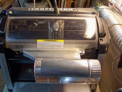
Perfect View – Clear vision of the carving area, dust free, with either a slight modification to the cover or pins to aid close the switches. Modification of the cover DOES NOT! void warranty.
5
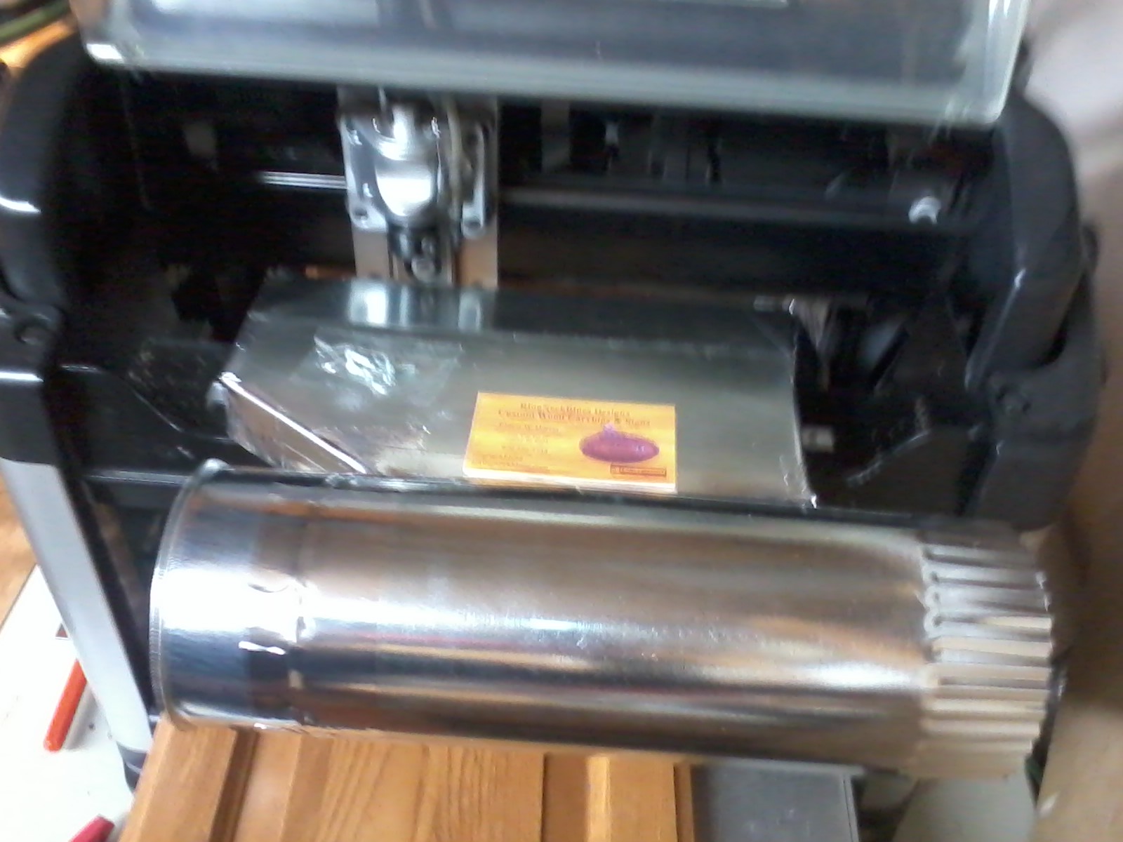
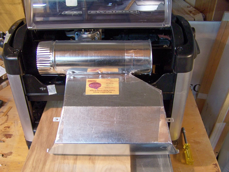
Simple Installation – Easy install and removal by 2 screws attached to the mounting plate. The holes have been pre-drilled by LHR. Simply insert the unit and attach the two screws included with the DC Insert.
6
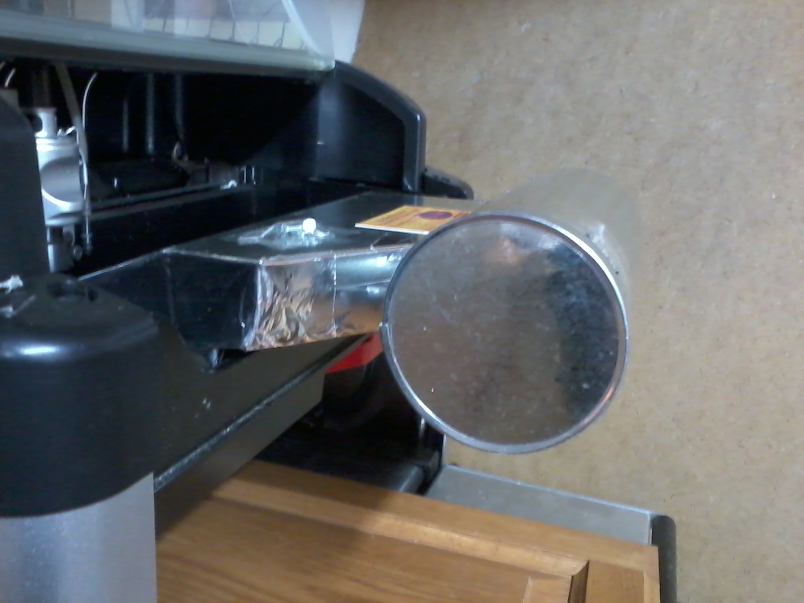
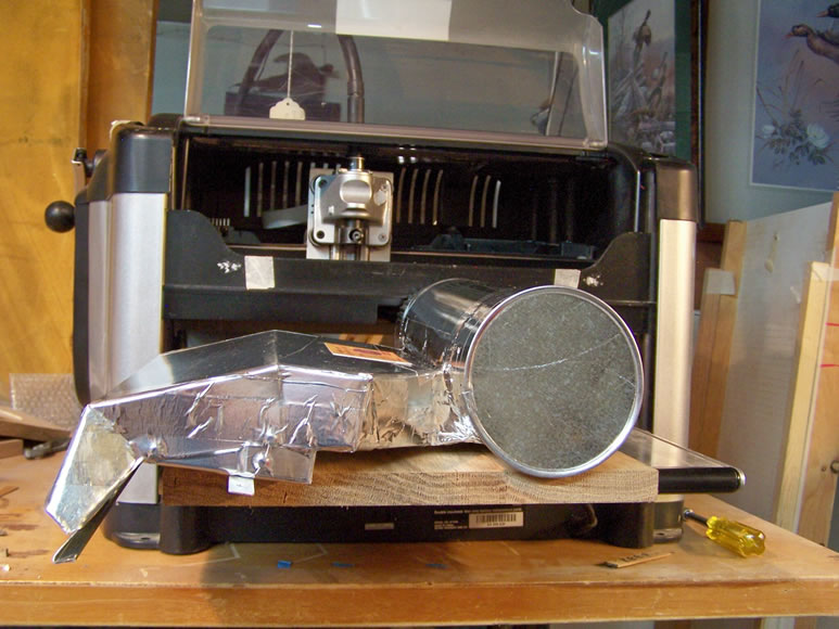
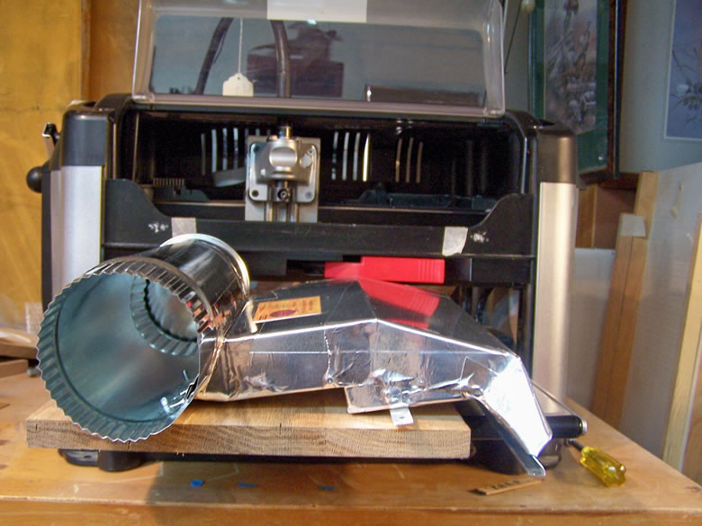
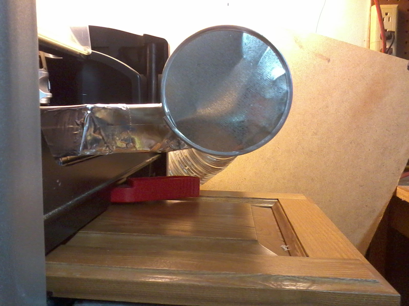
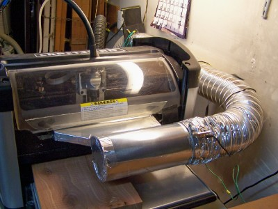
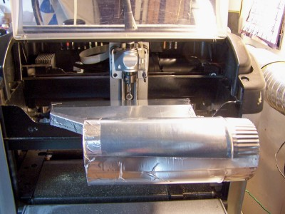
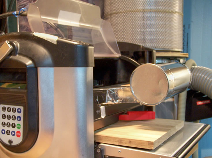
Easy Connection – 4″ straight dust collector connection is offset to the non keyboard side of the CW. Hook up to your dust collection system or a shop vac.
The DC Insert Has Been Approved By LHR/Carvewright As A 3rd Party Add-On


Download the latest version DC Insert instructions v4
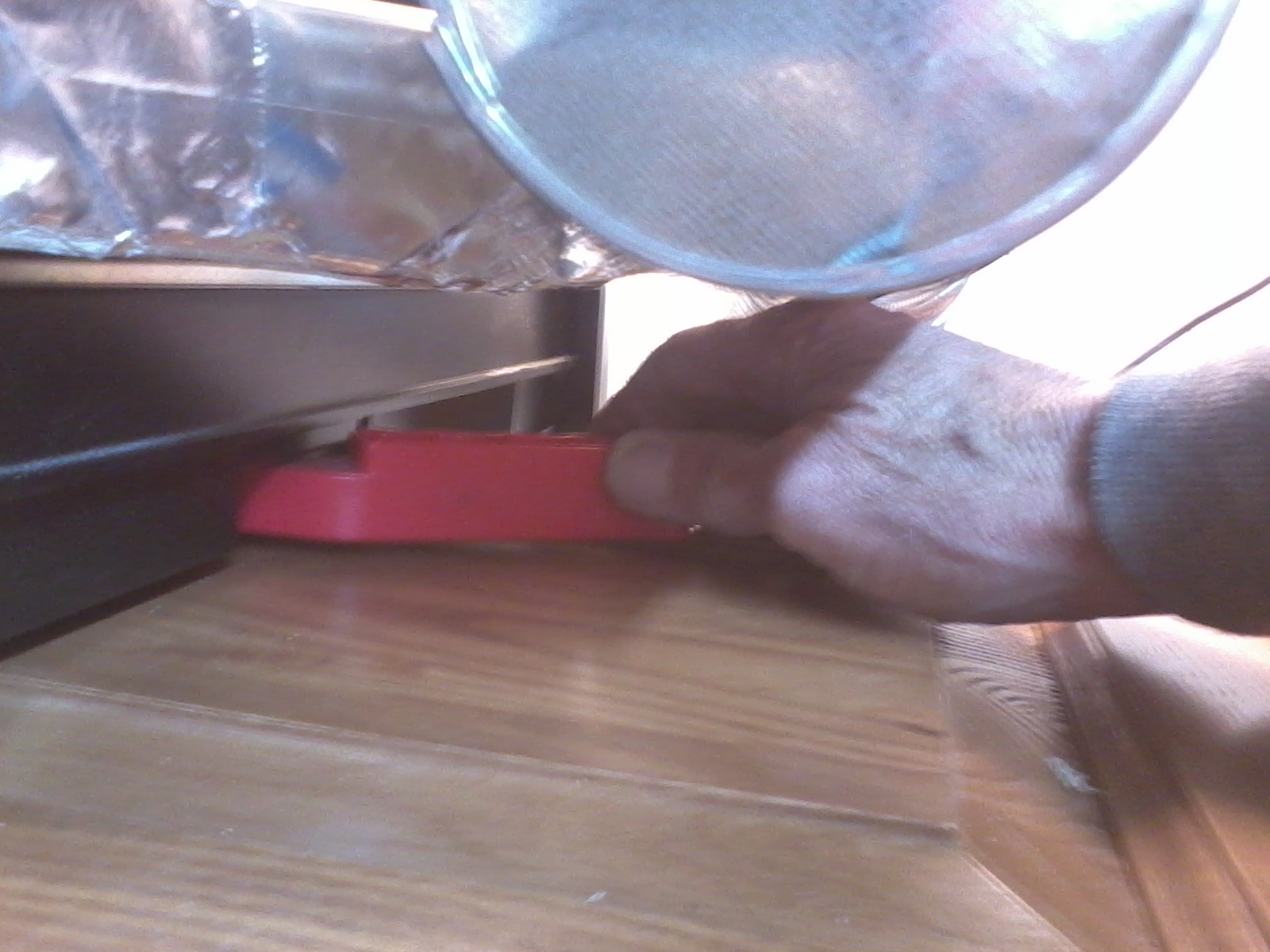
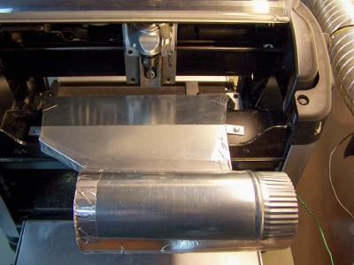
Install the insert into the CW/CC, insure the lip on the front of the insert slides over the bottom rail of the frame above the compression roller.
Pull back and lower the insert to insure it is in place.
Install and tighten the TWO 4 MM screws to hold the insert in place.
To check for proper installation, lightly lift up on the insert to make sure it does not move.
With the power off on the CW/CC move the Z-Truck back and forth and raise/lower the cutting head to insure it does not come in contact with the front of the insert.
For hooking up to your dust collections system I recommend
using the light weight aluminum dryer vent hose
The modification to the clear cover does not void any machine warranty.
Install the DC-Insert into the CW.
Mark a line on each side of the frame 1/16″ to 1/8″ above the top of the DC-Insert.
Remove the DC-Insert and close the door.
With a straight edge or ruler transfer the marks to the door.
The door can easily be cut to size with a dremel/rotary tool with a cut off wheel. Make sure you support the door and cover the inside of the CW. File or sand down the cut off edge of the door
to remove any burrs.
Looking at how the cover tabs match up to the switches it looks like a very simple solution by adding an extension to the tabs. Taping or gluing a thin shim to the leading edge of the tab (long flat area of the tab that pushes against the switch plunger) or using a hot glue gun to build up the tab it will make the contact for the switch and hold the cover off of the insert. The plunger on the switch extends just enough out of the cover frame so that when the cover is closed the tab pushes the plunger in. The length of the tab is more than the area of the plunger so that the tab in fact rests against cover frame. The shim does not need to be very thick, what I used as a test was a small piece of 3/16” dowel to give you an idea of the thickness.